
Software for Viking Orbiter TV experiment.
Program VikingOrbiterView is created for Viking Orbiter Raw Image Archive on CD-ROM (PDS).
Data set id: NSSDC ID PSPA-00073. Other id: 75-075A-01c, 75-075A-01d, 75-083A-01a, 75-083A-01b.
The Viking Orbiter images are arranged on the CD's in chronological order for each Orbiter,
grouped by orbit number. There are 32 CD's with Viking 1 Orbiter images (VO_1001 to VO_1032)
holding over 34,200 frames and 14 CD's for Viking 2 (VO_1051 to VO_1064) with over 15,600 images.
These CD-ROMs contain raw images taken by the Visual Imaging Subsystems (VIS) on NASA's twin
Viking Orbiter spacecraft to Mars. These images are copies of the Experiment Data Record (EDR)
images. No processing has been performed on the EDR image data. Thus, processing to perform
radiometric and geometric calibration, removal of noise, and interpolation of missing data may
be required to interpret the images.
The EDR image data are stored on CD-ROM in a compressed format that allows exact reconstruction
of the original images. The average Viking Orbiter image is compressed by a factor of about 3.5.
The EDR images in this archive have not been processed in any form other than organizing
the original telemetry into raster formatted files and compressing the image data using
First-Difference Huffman encoding algorithm.
This data set is available:
from National Space Science Data Center (NSSDC)
http://nssdc.gsfc.nasa.gov/
online on CD or DVD in a jukebox at the PDS Central Node.
http://www-pdsimage.jpl.nasa.gov/PDS/public/resources/cd_viking.html#vkoEDR
or on PDS online data volumes
http://pds-imaging.jpl.nasa.gov/Admin/resources/cd_viking.html#vkoEDR
Example 1.
Viking Orbiter 1 - Marineris Vallis.
Program options
Buttons

Visual Imaging Subsystem.
Each Viking Orbiter was equipped with two identical vidicon cameras, called the Visual Imaging Subsystem.
Each VIS camera consisted of a telescope, a slow scan vidicon, a filter wheel and associated electronics.
The angular field of view of camera as defined by the reseau pattern was 1.51 by 1.69 degrees.
A digital image was generated by scanning the vidicon face plate. The signal at each location (pixel)
was digitized as 7-bit number and converted to 8-bit number by multiplying by 2. A full-resolution,
uncompressed Viking image consist of an array of 1056 lines with 1204 samples in per line.
Each VIS camera contained a filter wheel with five color filters and a clear position (no filter).
The filter bandwidith are approximately:
Compressed Viking Orbiter image structure:
Steps for image decompression:
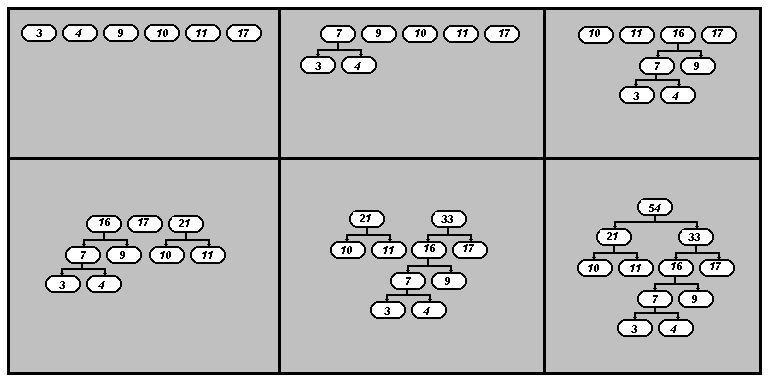
Huffman tree example.
Suppose we know that the frequency of occurrance for six item A-3, B-4, C-9, D-10, E-11, F-17
To build the Huffman tree, we sort the frequencies into increasing order (3, 4, 9, 10, 11, 17). Then we
choose the two smallest values, 3 and 4, and construct a binary tree with labeled edges.
Next, we replace the two smallest values 3 and 4 with their sum, getting a new sequence, (7, 9, 10, 11, 17). We again take the
two smallest values, 7 and 9 and construct a labeled binary tree.
We now have the frequencies (16, 10, 11, 17) which must be sorted into (10, 11, 16, 17) and the two lowest
are selected once again.
Decompression involves re-building the Huffman tree from a stored frequency table, and converting
its bit streams into characters. You read the file a bit at a time. Beginning at the root node in
the Huffman Tree and depending on the value of the bit, you take the right or left branch of the
tree and then return to read another bit. When the node you select is a leaf (it has no right
and left child nodes) you write its character value to the decompressed file and go back to the root
node for the next bit.
In this example: 0 - right branch 1 - left branch
A (probability 3/54) - 0111, B (probability 4/54) - 0110, C (probability 9/54) - 010,
D (probability 10/54) - 11, E (probability 11/54) - 10, F (probability 17/54) - 00
 |
 |
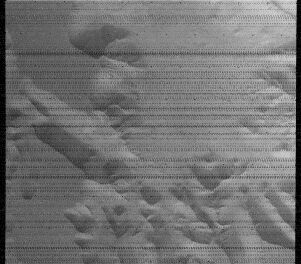
A common pattern of missing data is series of vertical bars with zero value pixels spaced
at an interval of 7 samples. The 7-sample interval results from the raw data being stored
on the spacecraft and transmitted to Earth in packets that contained every seventh pixel.
In addition, data for a few horizontal image lines may be missing and such lines are filled
with zero values.
 |
 |
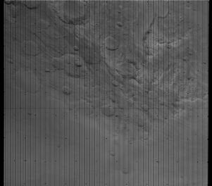
If the amount of mising data and noise is large, noise removal may be needed to make the image viewable.
|
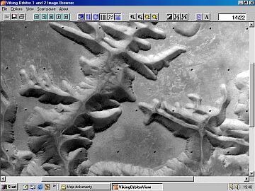
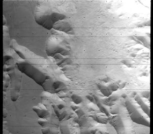
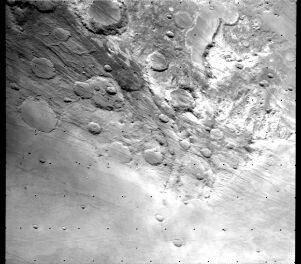
Oblique view obtained by Viking Orbiter 1 showing the heavily cratered terrain.
Heavily cratered terrain occurs mostly in the southern hemisphere. Horizon in the
background shows haze layers 24-40 km high, thought to be crystals of carbon dioxide. Viking Orbiter frame F101A32. |
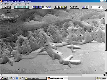
Example 4.
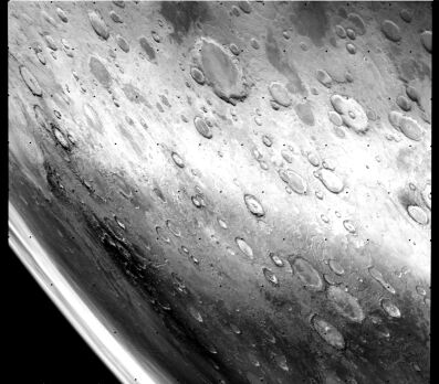
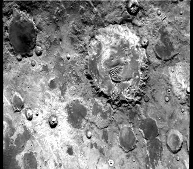
Cratered upland.
|
Cratered southern upland - scene typical at latitudes above about 30 degrees. The rims of many
large craters are rounded and softened. Viking Orbiter frame F093A47. |
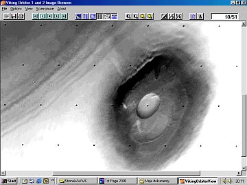
Example 5.
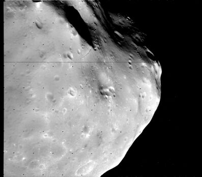
View of the martian moon, Phobos.
|
View of the martian moon, Phobos, showing grooved and cratered surface. The albedo, spectral
reflectance and low density of both martian moons suggest that they have a composition
similar to carbonaceus chondrites. Viking Orbiter frame F250A68. |
Cassini Orbiter Image Viewer ( New )
Venera 15 and 16 Radar Mosaic Browser
Other Links :
Mariner IV First Flyby of Mars - by JPL engineer William L. Momsen
For questions about this program, please contact:
mailto:piotr.a.masek@pro.onet.pl
Acknowledgements
I would like to thank:
visitors since 2003.06.06
![]()
Last Updated: 2003.06.06
Go Back to Main Menu